














1. Introduction to the issue of temporary power supply
A portable distribution unit (RUSP) takes in a 380/220 V, 50 Hz supply and distributes it to tools and equipment through industrial and domestic sockets, protecting every outgoing line with a circuit breaker and an RCD. What sets it apart from a stationary panel is the carrying handles or frame, the impact-resistant enclosure and an incoming cable with a plug instead of a terminal connection.
According to GOST IEC 61439-1-2013 "Low-voltage switchgear and controlgear assemblies" (for construction site boards – GOST IEC 61439-4), portable panels must have a rigid construction, resistance to mechanical impacts, and guarantee reliable protection of the operating personnel. The need to buy a RUSP arises whenever a stationary cable network cannot be deployed due to the dynamically changing work front. The RUSP mechanization panel makes it possible to rapidly scale the infrastructure, minimizing the downtime of process equipment.
2. Classification of the RUSP by rated current and power characteristics
The choice of the rated current of the RUSP's input device is a determining factor in its reliable operation. Errors at this stage lead either to systematic nuisance tripping of the protective automation or to thermal damage to the live parts. In modern electrical engineering practice, the most in-demand modifications are the RUSP 63A, RUSP 80A and the RUSP 100A panel.
To determine the required rated current, one must calculate the total installed power of the consumers, taking into account the simultaneity factor. The calculation is performed using the formula for a three-phase unbalanced or balanced load:
Where: I is the calculated line current (A); P is the total active power (W); U is the line voltage of the network (380 V); cosφ is the power factor of the consumers (for construction power tools and electric motors, it is taken on average as 0.85). Showing the course of the calculation: if a construction site simultaneously operates a 15 kW heat gun, a 5.5 kW concrete mixer and a 10 kW welding inverter, the total power is 30.5 kW (30,500 W). Calculation of the current:
Consequently, for this equipment configuration, the minimum permissible choice is the RUSP 63A unit. If there is a reserve for expanding the equipment fleet, it is advisable to choose the next step up – the RUSP 100A panel.
| RUSP rated current (A) | Maximum apparent power S (kVA) | Maximum active power P (kW) at cosφ=0.85 | Recommended cross-section of the input copper cable (mm²) |
|---|---|---|---|
| RUSP 32A | 21.1 | 17.9 | 6 |
| RUSP 50A | 32.9 | 28.0 | 10 |
| RUSP 63A | 41.4 | 35.2 | 16 |
| RUSP 80A | 52.6 | 44.7 | 25 |
| RUSP 100A | 65.8 | 55.9 | 35 |
3. Phase configuration and topology of connection schemes
The technical parameters of the RUSP's internal circuit determine the number and type of connected consumers. Common schemes are designated by matrix indices indicating the number of poles and the ratings of the output sockets (for example, 3x16, 6x1p, 2x3p). The scheme marking 3x16 means the presence of three three-phase connectors with a rated current of 16 A. Schemes of the 6x1p type indicate six single-phase sockets (1 pole + neutral + ground) distributed across the phases to prevent voltage imbalance.
Chapter 7.1 of the PUE requires an even distribution of single-phase loads across the phases. It sets no numerical threshold: voltage imbalance is regulated by GOST 32144-2013 through the negative-sequence and zero-sequence imbalance factors. Exceeding this threshold causes a neutral shift and the appearance of hazardous potentials on the metal housings of equipment. A modern RUSP distribution unit is equipped with internal N and PE busbars that are separate throughout the entire circuit (the TN-S or TN-C-S grounding system), which completely eliminates the risks of electrical injury in the event of a phase imbalance.
4. Assessment of the climatic version and the enclosure's protection rating (IP)
The conditions of operating portable panels outdoors predetermine strict criteria for the tightness of their enclosures. The international standard IEC 60529 (implemented in Russia as GOST 14254-2015) establishes the protection ratings (IP). For outdoor operation, the minimum permissible rating is IP44; however, for the harsh conditions of construction sites, an IP54 rating or higher is recommended.
The IP44 rating guarantees protection against the ingress of solid particles with a diameter greater than 1 mm and protection against water splashing from all directions. At the same time, the IP54 rating provides partial protection against fine construction dust (cement, gypsum, sand) which, accumulating on the contact groups of circuit breakers, can cause their failure or local overheating, as well as protection against water splashes. In conditions of intense precipitation, IP44 panels require an additional canopy, whereas IP54 models can be mounted directly on scaffolding elements or mobile stands.
5. Requirements for protective automation and switching devices
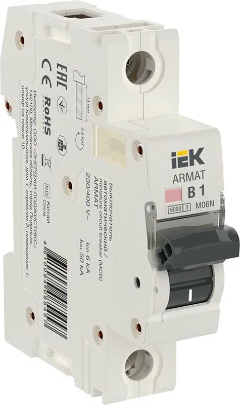
The internal contents of the RUSP must meet industrial safety requirements. The input device (a load break switch or a circuit breaker) must fully disconnect the entire circuit of the panel. Each outgoing line must, without exception, be protected by an individual circuit breaker corresponding to the rating of the connected socket.
Special attention is paid to residual current devices (RCDs/UZO) or differential circuit breakers. Clause 7.1.71 of the PUE recommends providing an RCD on socket outlet lines; the setting of no more than 30 mA is established by clause 7.1.79, and an RCD becomes mandatory under clause 7.1.82 – for sockets installed outdoors and in premises of particular danger or increased danger. Leakage currents exceeding 30 mA pose a mortal danger to a person, causing cardiac fibrillation. For the main lines inside the RUSP 100A panel, the installation of a selective RCD with a setting of 100–300 mA is permitted to prevent ignition of cable assemblies in the event of damage to their outer insulation.
6. A practical algorithm for selecting a RUSP for an industrial facility
For accurate equipment selection, engineering and technical personnel must follow a step-by-step protocol:
Step 1: Compiling a complete specification of the consumers, indicating their rated power (kW), starting currents and number of phases (220/380 V). The data are gathered from the manufacturers' data sheets.
Step 2: Calculating the aggregate consumption current using the demand factor (Kd): for construction sites with a variable operating mode it is taken from the site power supply design, usually in the range of 0.6–0.7.
Step 3: Determining the type of housing. Where there is a high probability of mechanical impacts (movement by crane, dropping of a tool), housings made of impact-resistant ABS plastic, polycarbonate, or steel with powder coating of at least 1.2 mm thickness are chosen.
Step 4: Verifying the connectors. The sockets must comply with the GOST IEC 60309-1-2016 standard. The use of household sockets without protective covers in portable distribution units for industrial purposes is prohibited.
7. Maintenance regulations and thermal imaging diagnostics of the RUSP
During industrial operation, portable distribution units are subjected to cyclic thermal and electrodynamic loads. In accordance with the Rules for the Technical Operation of Electrical Installations of Electric Power Consumers (Order of the Ministry of Energy of Russia No. 811 of 12 August 2022), distribution panels are subject to periodic thermal imaging and instrumental inspection. This procedure is necessary to detect local overheating zones arising as a result of the degradation of contact connections or the systematic overloading of the modular automation. Maintenance acts as a critically important preventive measure against the occurrence of arc short circuits and subsequent fires.
The physical process of insulation degradation under the influence of excessive thermal loads is described by empirical relationships derived from the Arrhenius equation. The basic engineering rule for polymer dielectric insulation (in particular, polyvinyl chloride compound) states that exceeding the long-term permissible operating temperature by every 8–10 °C reduces the service life of the dielectric by approximately a factor of two (the empirical Montsinger rule, which is an engineering approximation of the Arrhenius dependence rather than an exact regulatory value). For an objective demonstration of this physical process, below is a step-by-step calculation of the reduction in the service life of the live conductors inside the RUSP:
Step 1: Determining the baseline parameters. According to GOST 31996-2012, the long-term permissible heating temperature of the conductors of power cables with PVC insulation is +70 °C. When the temperature regime is observed, the cable service life under the manufacturers' technical specifications is 30 years. GOST 31996-2012 (clause 5.2.6) does not assign a specific value but sets the series 25, 30, 35 and 40 years, from which the specification for a given cable type selects one; the warranty period of operation under Section 11 is 5 years.
Step 2: Recording the actual operating parameters. Suppose that during routine thermal imaging inspection it was found that, due to the loosening of the screw clamp of the input circuit breaker, the temperature of the copper conductor at the contact point reached +100 °C.
Step 3: Calculating the temperature delta. The difference between the actual and the standard temperature is calculated as:
Step 4: Calculating the thermal aging acceleration factor. The number of 10-degree intervals of excess is:
The service-life reduction factor is calculated as the base 2 raised to the power of the number of intervals:
Step 5: Determining the actual residual service life. The expected service life of this section of wiring up to the moment of guaranteed thermal breakdown of the insulation will be:
In addition to the thermal regime, Chapter 1.8 of the PUE (clause 1.8.37, Table 1.8.34) sets the standards for measuring the insulation resistance of live parts.
The measurements are carried out with a specialized, calibrated megohmmeter generating a test voltage of 1000 V (or 2500 V for high-power input supply circuits). The standard value of the insulation resistance of each phase connection inside the RUSP must be at least 0.5 MΩ. If the readings recorded by the instrument fall below this threshold, operation of the device is categorically prohibited. A drop in resistance below 0.5 MΩ indicates critical drying of the polymer layer, the appearance of microcracks, or the presence of hygroscopic conductive dust inside the sealed housing. In such situations, the panel is subject to immediate dismantling, complete disassembly, convection drying and replacement of the damaged sections, with the mandatory drawing up of a technical defect report. Tightening of the contact groups is carried out with a torque tool set to the torque specified in the device data sheet.
View in catalog: Construction Site Distribution Board, Complete Switchboard Equipment, Power Connectors, Modular Circuit Breaker (MCB).